A 20-ton crane does not have a 20-ton permission at every boom angle and working radius, so an IoT dashboard cannot safely rely on a single tonnage reading. You will be able to trace the sensor-to-cloud connection, define the data and safety boundaries, and specify an integration that still protects the crane when the network fails.
Key takeaways
- Confirm the LMI measures both lifted load and crane geometry.
- Connect sensors to the controller, then link the controller to an IoT gateway.
- Transmit load, radius, boom angle and alarm status to the dashboard.
- Specify local overload protection that works when the network fails.
What the 20 Ton LMI Measures Before It Sends Data
A 20-ton LMI measures load and crane geometry before it sends data. That makes it different from a load-only indicator.
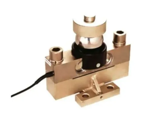
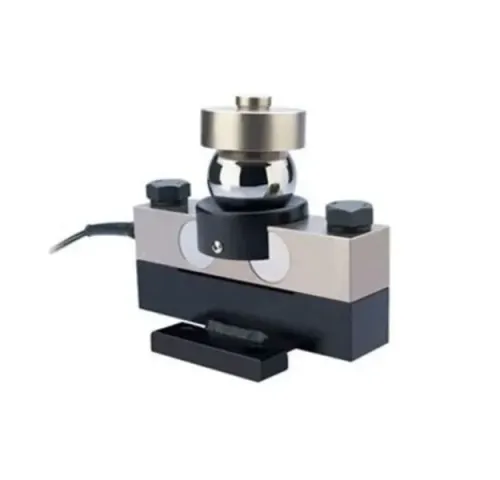
The load value comes from a load cell, line-tension sensor or hydraulic-pressure measurement. Boom angle and boom length establish the crane geometry; the controller then calculates or measures the operating radius.
Load moment equals lifted load multiplied by working radius. The controller compares that result with the rated-capacity chart for the selected crane configuration, then calculates utilization and triggers local alarms when limits are approached or exceeded.
“20 ton” is a headline capacity, not a permitted load at every radius. The allowable value changes with boom length, outrigger position, attachment, counterweight and reeving arrangement. A wrong angle or length signal can therefore make a plausible load reading produce a wrong capacity result.
| System | What it measures or calculates | What it does not prove |
|---|---|---|
| LMI | Load moment, utilization, configuration-specific capacity and alarms | That every configuration permits 20 tons |
| Load-only indicator | Load or line tension | Working radius or rated-capacity compliance |
| GPS or operating-hours tracker | Location, engine hours and fleet activity | Current load moment or overload protection |
A load moment indicator IoT system must transmit load, radius, boom angle, boom length, active configuration, utilization and alarm state, not just tonnage. Without those fields, an IoT load monitoring crane dashboard is fleet telematics with a number attached, not evidence of current lifting safety.
The Physical Connection: Sensors, Controller, Display and Gateway
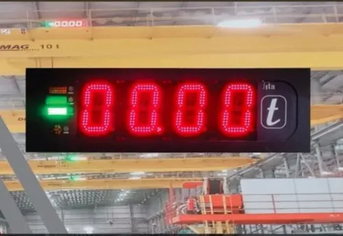
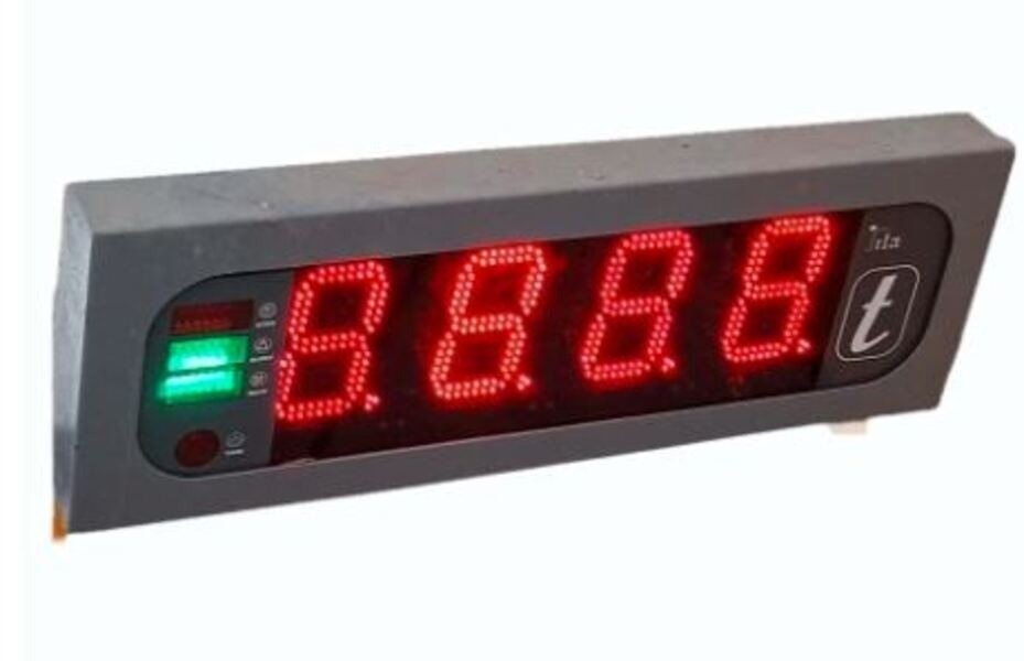
The connection path starts with load, boom-angle, boom-length, reeving, outrigger and configuration inputs feeding the onboard LMI controller. The controller drives the cab display, buzzer, warning lamps and any validated limit or cut-off function. A communication port then feeds an edge gateway, which sends selected telemetry to an edge server or cloud platform.
Confirm the physical interface from the LMI wiring diagram and protocol documents. Ask these questions before purchasing:
- Does the 20 ton LMI provide a native IoT interface, or does a separate gateway read the controller?
- Is the port RS-485 with Modbus RTU, CAN bus, Ethernet, Wi-Fi or a gateway with 4G?
- If the LMI exposes Modbus RTU or CAN, does the gateway convert that protocol to MQTT or an API?
- Which registers, messages, scaling factors, alarm states and configuration values are documented?
- Does the gateway support the crane’s power supply, connector type, enclosure and site network?
The gateway performs protocol conversion when the LMI does not provide an internet-ready interface. For a 20 ton LMI in Pune, the communications choice affects data availability, not the load calculation.
A load moment indicator IoT system must keep its deterministic control loop onboard; Wi-Fi, cellular service or cloud response must never be required for local overload protection.
What Travels from the Crane to the IoT Dashboard
The onboard controller samples the load, boom angle and boom length, then calculates the current operating values. The gateway validates each record, adds a trusted timestamp, and stores it locally when cellular or plant-network service fails. MQTT, HTTPS or another documented protocol forwards the buffered records after communication returns.
A useful dashboard payload includes:
- Crane identity, timestamp, measured load, rated capacity from the active chart, load percentage and working radius.
- Boom angle, boom length, active crane configuration, operator or job reference, overload alarm and sensor-health state.
- The reason for any limit or shutdown event, including the configuration and sensor condition that existed at the time.
MQTT QoS 1 or QoS 2 improves delivery assurance; it does not make communication real-time or replace local LMI protection. Define retained-message behavior, session handling, offline storage duration and duplicate-record rules before deployment. The dashboard must distinguish a retransmitted record from a new measurement.
Use authenticated device identities, TLS encryption, asset-level authorization and replay protection. Permit outbound telemetry by default; protect any cloud-to-crane command with separate authorization and audit controls.
If the gateway joins a plant network, place the controller, gateway, enterprise network and cloud in IEC 62443 zones connected by controlled conduits, not on one unrestricted network. This architecture suits an IoT load monitoring crane and a crane IoT system in Pune without making the dashboard responsible for overload safety.
How the LMI Handles a 20 Ton Limit and a Lost Network
A 20-ton limit is not a universal permission to lift 20 tons. Configure the LMI with the crane manufacturer’s rated-load chart for each boom length, working radius, outrigger condition, attachment, counterweight and reeving selection.
The controller compares measured load moment with the permitted value for the selected configuration. If the limit is reached, it activates the local display, audible alarm and any specifically designed and validated cut-off function.
A cloud dashboard can report the alarm and preserve its history, but cellular, Wi-Fi, MQTT or cloud failure must not remove local overload protection.
Use this field checklist before accepting a 20-ton load moment indicator IoT system in Pune or a 20-ton LMI in Pune:
- Confirm the operator selected the correct parts-of-line or reeving arrangement.
- Confirm the correct load chart, attachment, counterweight and outrigger condition.
- Check for drifting boom-angle or boom-length feedback.
- Inspect load-cell wiring for cuts, loose connectors, crushed sections and overload damage.
- Verify that calibration has not expired and that the displayed sensor-health state is normal.
Store an event record that identifies the crane, chart revision and active configuration, together with the calibration status and sensor-health state. Include the measured load moment, permitted value, alarm or shutdown reason and timestamp. Without these fields, a dashboard can preserve precise-looking numbers while failing to prove which chart or sensor condition produced them.
What to Specify When Connecting a 20 Ton LMI in Pune
Before approving a 20 ton lmi in pune, turn the quotation into a compatibility schedule rather than accepting nominal tonnage or a dashboard screenshot.
1. Record the crane make and model, boom-length and attachment ranges, reeving and outrigger options, and the rated-load charts for every operating configuration. Request the load-cell, angle, length and pressure-sensor types, wiring diagram, display and alarm behavior, local shutdown philosophy, and calibration procedure.
2. Confirm whether the LMI has a native IoT interface or needs a separate gateway.
Specify RS-485 with Modbus RTU, CAN, Ethernet, Wi-Fi or 4G; identify who performs protocol conversion; and define the API, sampling rate and payload fields: crane identity, timestamp, load, radius, boom angle, boom length, rated capacity, utilization, active configuration, alarm, sensor health and shutdown reason.
3. Set the data rules in writing. Require an offline buffer sized for the longest expected outage, storage retention, timestamp handling, duplicate-record treatment and power-interruption recovery. A 20 ton load moment indicator iot system in pune still needs local protection when cellular, Wi-Fi or cloud service fails.
4. Check 4G coverage at every worksite, available Wi-Fi, enclosure and connector protection, temperature and vibration ratings, and service response times. Pune changes communications conditions, not the load-moment calculation.
5. Separate acceptance tests. Disconnect the network and prove local overload alarms and validated shutdown behavior; then test dashboard timestamps, alarms, configuration and event history. Evaluate SMARTITA PRIVATE LIMITED against this same schedule, as you would any crane iot system in pune.
Related product
Frequently asked questions
What does a 20-ton LMI measure before sending data?
It measures lifted load and crane geometry, including boom angle, working radius and related operating limits.
How does a 20-ton LMI connect to an IoT system?
Load and geometry sensors connect to the LMI controller, which feeds a display and an IoT gateway for dashboard transmission.
What data travels from the crane to the IoT dashboard?
The system can transmit load, boom angle, working radius, capacity or utilisation, alarm status and network or device faults.
What happens when the IoT network is lost?
The LMI must continue local measurement, display and overload warnings because safe crane operation cannot depend on a live network connection.
What should you specify for a 20-ton LMI IoT system in Pune?
Specify the crane configuration, 20-ton capacity basis, sensor inputs, local alarms, gateway interface, data fields, power supply and installation conditions.
Related product
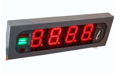 | Load Moment Indicators ₹62000 (LMI) Price: ₹62,000/Piece The 20 Ton Load Moment Indicator (LMI) from SmartITA Pvt. Ltd. View product → |