A 1-ton rating tells you the sensor’s capacity, not the payload a robot can measure accurately or safely throughout its motion. By defining the force path, checking dynamic loads and specifying the complete electrical and calibration chain, you can compare a digital load cell with the interface your robotic system actually needs.
Key takeaways
- Measure the force path, not simply the payload, before selecting a load cell.
- Treat a 1-ton rating as capacity, not proof of accurate readings during motion.
- Specify overload protection, output protocol, sampling rate and environmental limits.
- Validate readings under real acceleration, contact, friction and cable-drag conditions.
Choose the measurement point before choosing the load cell
Define the physical quantity at the measurement point before comparing a ton digital load cell for robotic solution in pune. A cell beneath a fixture measures the fixture reaction along its sensitive axis; it does not distinguish payload weight from clamp force, contact force, friction, acceleration or cable drag.
Robotic load measurement in pune therefore starts with the question: what must the reading represent?
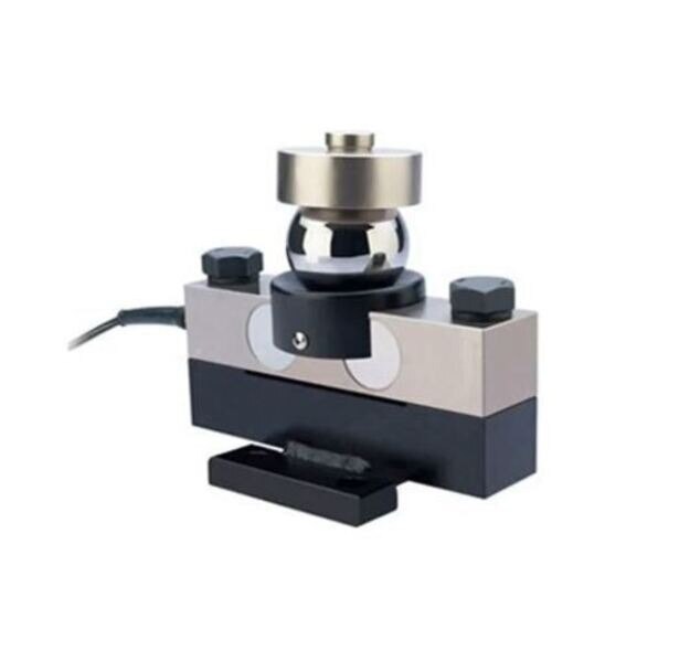
- Mount a single-axis compression cell beneath a rigid fixture when you need payload, fixture reaction or hopper weight. Use a flat base, centred load-introduction plate and rigid adapter plates to keep the force aligned.
- Use a tension arrangement for a suspended load, with the cell carrying the load directly rather than through a side-loaded bracket.
- Choose a multi-axis force/torque transducer at the wrist when the application must resolve force and moments during contact, gripping or tool interaction. A compression cell cannot replace it.
| Measurement target | Suitable arrangement | Main limitation |
|---|---|---|
| Payload or hopper weight | Compression cell below the vessel or fixture | Motion and friction appear as additional force |
| Suspended tooling load | Tension cell in the load path | Side loads and swinging distort the reading |
| Clamp or gripping force | Cell integrated into the clamp mechanism | It does not equal payload weight |
| Wrist contact force and torque | Multi-axis force/torque transducer | A single-axis cell misses bending moments and off-axis forces |
Uneven mounting, bending moments, off-axis forces and a cable pulling against the sensor create apparent load. Centre the load path and provide cable strain relief before increasing capacity.
What a 1-ton rating means in a moving robot
A 1 ton rating is the cell’s rated capacity, not a permitted continuous overload and not the useful range for every load. For a 1 ton digital load cell in Pune, calculate the complete force-time envelope: tare weight, payload, tool weight, acceleration, stopping, gripping impact, transfer vibration and collision forces.
Compare that envelope with each limit:
| Limit | What it means | Selection use |
|---|---|---|
| Rated capacity | Specified continuous measuring capacity | Keep the working peak within this value |
| Safe overload | Overload the cell can withstand without unacceptable permanent error | Check against foreseeable impact and eccentric loading |
| Ultimate overload | Point at which mechanical failure can occur | Never use it as operating capacity |
Leave enough range to resolve the smallest load that matters. A cell sized only for the average payload can saturate during a stop; a higher-capacity cell can then hide small changes through poorer resolution.
Eccentric loading, bending moments, shock loading and cable drag create apparent force. A larger cell does not correct a bent or off-centre load path; use a rigid, centred mounting arrangement first. Robotic load measurement in Pune must also account for warm-up and thermal gradients passing through the mounting structure.
Ask for the compensated temperature range, zero-temperature coefficient, sensitivity-temperature coefficient and stabilization procedure. The practical choice is a cell that survives the dynamic peak while still resolving the intended working load.
Specification and communication checklist for Pune integration
For a digital load cell for robotic solution in pune, request a complete datasheet and controller wiring diagram. “Industrial” and “sealed” prove nothing without measured limits, an IP code tested under IEC 60529, and stated test conditions; the rating does not automatically cover connectors, cable joints or robot-side electronics.
1. Ask for rated capacity, rated output, combined error, repeatability, hysteresis, creep, resolution, excitation voltage, safe and ultimate overload ratings, cable length and operating temperature.
2. Request zero-temperature coefficient, sensitivity-temperature coefficient, compensated temperature range and warm-up or stabilization procedure. These figures matter more than the label on a 1 ton digital load cell in Pune.
3. Match the output to the controller: millivolt-per-volt analogue output needs a signal conditioner or controller-side analogue input; amplified voltage needs a compatible input; RS-485 may use Modbus RTU; CAN may use CANopen; Ethernet may use EtherNet/IP or PROFINET; IO-Link needs an IO-Link master.
A gateway is required when the cell protocol does not match the PLC.
4. For a ton digital load cell for robotic solution in Pune, ask for sample rate, update rate, conversion latency, filter delay, timestamp behaviour and resolution at the configured range. Digital output alone cannot prove suitability for collision detection or force control.
5. Require IEC 61326-1 EMC information and installation instructions covering grounding, shielding, isolation and separation from motor wiring.
SMARTITA PRIVATE LIMITED can be one supplier in your comparison, but request these integration details from every candidate before selecting the sensor.
Related products
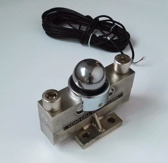 | Digital Load Cell ₹72000 Price: ₹72,000/Piece The 30 Ton Digital Load Cell from SmartITA Pvt. Ltd. View product → |
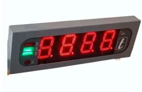
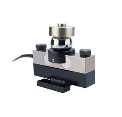 | Digital Load Cell ₹45000 Price: ₹45,000/Piece The 1 Ton Digital Load Cell from SmartITA Pvt. Ltd. View product → |
Install the sensor without corrupting the reading
A flat, rigid base and a centred load-introduction plate keep force on the sensing axis instead of turning it into bending. Mount a compression cell beneath the fixture, or use the tension orientation for a suspended load; reversing the arrangement can produce a wrong or unstable reading.
- Machine the base and adapter plates flat, then centre the load path over the cell’s sensing axis.
- Tighten fasteners in a controlled, documented sequence and torque them to the sensor or adapter specification. Do not let bolts, brackets or hard stops carry force around the sensing element.
- Leave clearance around the cell so the frame, fixture or cable cannot contact another surface under deflection.
- Route the cable through strain relief without pulling on the cell. Keep it away from robot joints, pinch points, hot surfaces and repeated bend zones.
- Protect connectors and cable joints separately. An enclosure’s IP code, interpreted under IEC 60529, does not automatically cover an exposed connector, joint or robot-side electronics.
Robot acceleration, vibration, tool movement and impact appear in the signal. Decide whether robotic load measurement in Pune requires static payload, peak force or dynamic force control before choosing the filter.
Use mechanical isolation, slower test moves, controlled acceleration and a rigid tool arrangement to separate payload from motion effects. Filtering can reduce vibration, but it adds delay and cannot correct saturation, a loose mount or an unsuitable sensor. A digital load cell for robotic solution in Pune is only as reliable as its load path.
Calibrate, validate and connect readings to robot action
Prove the installed chain—not just the sensor—before allowing a robot action. For a 1 ton digital load cell in Pune, the calibration result belongs to the mounted cell, adapter, cable, gateway and controller together.
1. Warm the assembly to its operating condition, then record the unloaded zero. Document the temperature and stabilization time.
2. Apply several traceable known loads across the working range, including the smallest critical load and the maximum planned load. Record increasing and decreasing readings to expose hysteresis.
3. Repeat each load through multiple cycles. Check repeatability, zero return after unloading and creep during a fixed-load dwell.
4. Apply a permitted off-centre load at defined positions. Reject the installation if eccentric sensitivity exceeds the agreed pass limit or indicates a bending load path.
5. Repeat the checks in the robot’s actual working poses. Cable routing, fixture flex and gravity components change with orientation, so a bench result alone does not validate robotic load measurement in Pune.
6. Test the specified temperature range, power cycling, communication timeout, corrupted data, sensor saturation and recovery. Confirm that the controller rejects stale or invalid values instead of converting them into a valid-looking command.
Define tare rules, zero tracking, sample rate, filtering delay, alarm thresholds and the action for a failed value. Do not use the load-cell reading as the sole protective function unless the complete sensing, wiring, diagnostics and reaction path meets the required safety design; ISO 13849-1 assesses that safety-related control system, not the sensor label.
Record the installed chain, test loads, poses, software version, temperatures and pass limits.
Frequently asked questions
Where should you place a load cell in a robotic system?
Place it at the defined measurement point in the force path, then account for fixture reaction, clamp force, friction, acceleration and cable drag.
Does a 1-ton digital load cell measure a robot’s payload accurately while moving?
Not by rating alone. Moving loads create acceleration forces, so validate the cell and filtering against the robot’s actual motion and force path.
What should you specify when integrating a digital load cell in Pune?
Specify capacity, overload protection, accuracy, excitation, output protocol, sampling rate, connector, ingress protection, temperature range and robot-controller compatibility.
How do you prevent installation errors from corrupting the reading?
Align the sensitive axis, keep loads within the intended force path, prevent side loading, protect cables from drag and verify the mechanical mounting.
How should you validate a load cell before connecting it to robot action?
Calibrate with traceable test loads, compare readings across the operating range, test motion and contact events, set limits, and confirm the robot’s response.
Related product
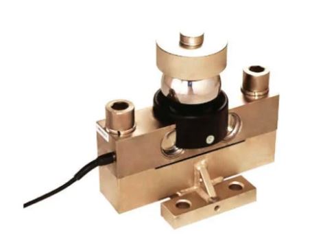 | Digital Load Cell ₹85000 Price: ₹85,000/Piece The 100 Ton Digital Load Cell from SmartITA Pvt. Ltd. View product → |