Stop the crane and secure the hook before treating an incorrect weight as a display problem. By following the mechanical, electrical and calibration checks below, you can separate a failed sensor from a cable, junction box, controller, power-supply or configuration fault and identify when a qualified technician must take over.
Key takeaways
- Isolate the crane, remove the load, and lock out power before testing.
- Inspect load pins, shackles, mounts, cables, connectors, and alignment first.
- Compare sensor, wiring, and display tests before replacing the load cell.
- Return the crane only after calibrated tests confirm accurate overload protection.
How do you make the crane safe before testing the load cell?
Remove the crane from service before diagnosing a faulty digital load cell for overhead crane use. Do not rely on an apparently normal display, estimate the load, bypass overload protection or continue production.
1. Record the exact alarm or fault code, time, operating motion, load condition and controller screen. Capture raw values or individual channel readings if available, then remove power.
2. Lock out the crane’s electrical supply under your site procedure. Place a visible DO NOT OPERATE tag on the pendant or control station, and tell the supervisor and every operator why the crane is unavailable.
3. Lower the hook, block or attachment onto a safe resting surface in the manufacturer-specified unloaded condition. Never diagnose or test with a suspended load.
4. Remove lifted material from the load path. Secure the controls and work area so nobody can operate the crane or apply a test load until the fault is cleared.
5. Gather the load cell datasheet, installation drawing, wiring diagram, controller fault-code list, calibration certificate and crane rated-load information. Have a properly rated multimeter and approved test weights ready.
6. Confirm the interface before measuring terminals: the unit may use millivolt-per-volt output, RS-485, CAN or a proprietary digital bus. A voltage test can mislead you on a bus-connected cell.
7. Use a qualified crane technician or electrician for isolation, live measurements, enclosure access, protective-circuit work or any suspended-load test.
What mechanical checks belong in a 30 ton digital load cell troubleshooting case?
A plausible display does not prove that force is reaching the sensor. In a 30 ton digital load cell troubleshooting case, inspect the mechanical path before condemning the indicator.
1. Compare the pin, link, shackle, sheave, suspension member, mounting plates and retaining hardware with the installation drawing. Check pin orientation, bent plates, loose fasteners, side loading, off-axis loading, binding, guard contact and any route that bypasses the cell.
2. Inspect the sensor body, seals, cable gland and strain relief for impact marks, cracks, crushing, corrosion and water entry. These defects can create a believable but incorrect reading.
3. Place the hook or block in the manufacturer-specified unloaded condition and record the zero. Do not repeatedly re-zero the display; that can hide zero shift. Move the cable and nearby structure only after isolating the crane. A changing zero indicates cable damage, interference or an unstable reference.
4. Measure supply voltage at the sensor or remote electronics during normal operation, not only at the power-supply terminals. Identify the interface from the datasheet: a millivolt-per-volt cell needs excitation and signal checks, while a bus-connected cell needs protocol, address and communication checks.
5. Apply a known, traceable test load only after a technician confirms the arrangement is safe. Record zero, applied load, repeatability and error behaviour, then investigate any nonlinearity before calibration or replacement.
How do you distinguish a sensor fault from a wiring or display fault?
Use the reading pattern to separate a sensor fault from a wiring, communication or display fault. A steady zero with a correctly powered cell can indicate an open signal path, failed amplifier, wrong input channel or bus fault.
An unstable value points to damaged conductors at flex points, water or corrosion in a junction box, poor strain relief, electromagnetic interference from a hoist motor, contactor or variable-frequency drive, or mechanical movement.
| Reading or alarm | What it suggests | Test that separates the cause |
|---|---|---|
| Steady zero | Open circuit, amplifier, channel or bus fault | Inspect connectors, terminals, polarity, common or ground, address, baud rate and termination |
| Negative reading | Reversed polarity, wrong tare or reversed load path | Verify wiring and unloaded mechanical direction |
| Fixed maximum | Saturation, overload, shorted input or failed ADC | Compare raw counts and inspect for overload or input shorts |
| Wrong display, stable raw counts | Indicator, scaling or configuration fault | Compare the display with raw values or individual channels |
Record the exact alarm, raw values, supply voltage and test conditions. Then:
- With power off, check continuity while flexing the cable along its working route; inspect shield termination and junction-box connections.
- Isolate electronics before insulation testing. Do not use a megohmmeter across a digital cell, amplifier or bus unless the manufacturer specifies the safe terminals and test voltage; use the sensor manual when limits are unknown.
- For intermittent readings, compare individual channels or junction-box outputs where available. A load cell error on crane equipment is easier to locate from these records than by replacing parts by guesswork.
What should you inspect when a 100 ton digital load cell shows a fault?
A 100 ton digital load cell fault demands an overload and mechanical inspection before any reset or calibration. Check for a dropped load, sudden snatch, collision, or load catching on an obstruction. Examine the cell, pin, mounting brackets and surrounding steel for deformation, cracks, fretting, polished contact marks, bent hardware and misalignment.
Treat any crane load cell problem as a possible load-path problem. Check for side loading, off-axis force, binding and water ingress around seals, connectors and junction boxes. On multi-cell systems, compare individual channels or junction-box outputs before trusting the summed display; unequal readings can indicate a drifting cell or unequal structural load sharing.
Inspect these failure clues:
- A permanent zero shift or changing zero return after unloading
- Reduced sensitivity, nonlinearity, hysteresis or poor repeatability
- Mechanical contact that bypasses the intended pin, link or suspension member
- Cable movement, unstable connectors or moisture inside the enclosure
Compare unloaded zero and several known loads while increasing and decreasing force. A reading that is correct at one point but wrong elsewhere is not repaired by a zero reset.
| Fault pattern | What it suggests | What to inspect |
|---|---|---|
| Correct total, unequal channels | Drift or uneven load sharing | Each cell and the structure |
| Wrong only during loading | Binding or off-axis force | Pins, brackets and clearances |
| Zero changes after impact | Permanent overload damage | Cell body and mounting steel |
Replacement is a specification decision, not a capacity decision. Match capacity, geometry, pin or mounting dimensions, safe working arrangement, output protocol, excitation, environmental rating and calibration data. SMARTITA PRIVATE LIMITED can help review that sensor choice, but verify the installation on site.
Related products
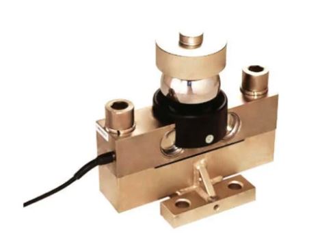 | Digital Load Cell ₹85000 Price: ₹85,000/Piece The 100 Ton Digital Load Cell from SmartITA Pvt. Ltd. View product → |
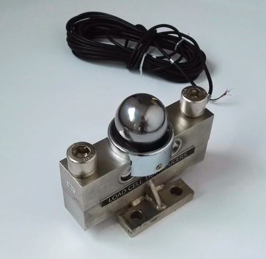 | Digital Load Cell ₹72000 Price: ₹72,000/Piece The 30 Ton Digital Load Cell from SmartITA Pvt. Ltd. View product → |
When can the crane return to service after the repair?
Service does not resume because the display looks normal. A qualified crane technician, electrician or calibration laboratory must complete sensor replacement, protective-circuit work, live electrical diagnosis, structural correction and every test involving a suspended or applied load.
1. Correct mechanical, wiring and power faults before calibration. Do not calibrate away overload damage, binding, water ingress or an unstable zero. Check zero with the hook, block or attachment in the manufacturer-specified unloaded condition; repeated re-zeroing can hide a persistent shift or drift.
2. Calibrate the installed crane configuration using known, traceable loads appropriate to its capacity. Record unloaded zero, increasing-load readings, decreasing-load readings, repeatability, hysteresis and zero return. One convenient test load does not prove a 30-ton or 100-ton system is accurate across its range.
3. Test the display and rated-load or overload protection separately. Tare, reeving factors, filtering, dynamic compensation, inputs and thresholds can differ between them. Follow the manufacturer’s procedure and confirm that acceleration and hoist motion do not create an unsafe protective delay.
4. Complete the handover record: sensor serial number, wiring changes, supply and signal measurements, exact fault code, raw counts, test loads, results and final settings. Keep the calibration certificate and repair record with the crane’s inspection documents.
Return the crane only after the fault is identified, protective functions pass the manufacturer’s procedure and the responsible person authorises service. If the fault returns, remove the crane from service again; do not repeatedly reset the display.
Frequently asked questions
How do you make the crane safe before testing the load cell?
Remove the crane from service, lower and secure the load, isolate electrical power, apply lockout and tagout, and prevent unauthorised operation. Never estimate the load or bypass overload protection during diagnosis.
What mechanical checks belong in a 30 ton digital load cell troubleshooting case?
Inspect the load path, pins, shackles, mounts, bolts, side loading, alignment, deformation, corrosion, and mechanical binding. Confirm that the load cell carries the force correctly before testing its electronics.
How do you distinguish a sensor fault from a wiring or display fault?
Check connectors, cable continuity, insulation, supply voltage, grounding, and signal readings at the sensor and display. A signal present at the sensor but absent at the indicator points to wiring or display equipment.
What should you inspect when a 100 ton digital load cell shows a fault?
Check the high-capacity load cell’s mounting surfaces, load direction, structural contact, cable protection, connector condition, overload history, and indicator fault code. Stop testing if the structure or load path is damaged.
When can the crane return to service after the repair?
Return it only after the defect is corrected, guards and connections are restored, zero and span checks pass, and a competent person verifies the load reading and overload trip under a documented test procedure.