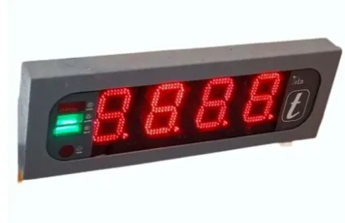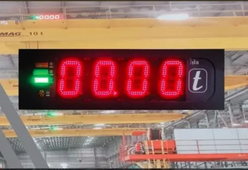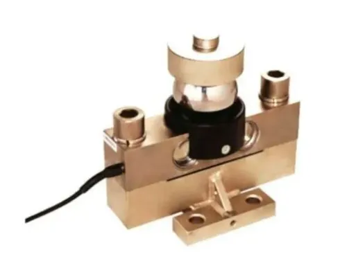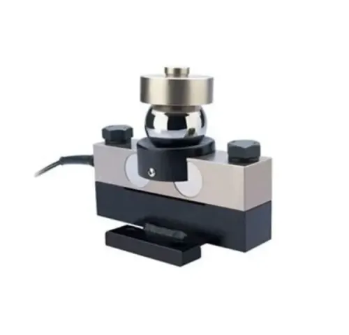
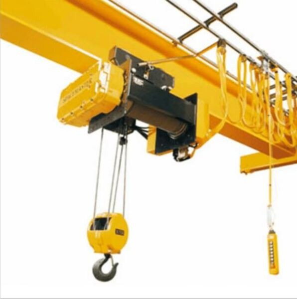
A crane load indicator turns force in the lifting path into a usable load signal, but the safety benefit depends on where it is installed, how it communicates with the control system and what happens when the reading is wrong or unavailable. By the end, you will be able to distinguish indicator types, select a suitable capacity and define the checks needed before connecting one to a Pune plant’s PLC or SCADA system.
Key takeaways
- Define the required safety function before choosing an indicator, SLI or LMI.
- Match the sensor range to rated capacity, including hook blocks and lifting attachments.
- Specify relay, analog, digital and alarm interfaces before ordering the system.
- Commission alarms, calibration and automation signals under controlled lifting conditions.
How a crane load indicator becomes an automation signal
A ton crane load indicator for industrial automation in Pune converts force in the crane’s load path into a load value. A load pin fitted at a sheave or hook measures strain, while a rope-tension sensor measures the force in the hoist line.
The sensor’s millivolt or digital output passes to signal conditioning, where calibration, tare and filtering produce the displayed hook load.
During lifting, the indicator updates as line tension changes. It must account for the hook block and accessories already hanging from the crane, or the operator will see a false payload. During lowering, the reading should remain stable as the load settles; sudden spikes from shock loading should not be hidden by excessive filtering.
If the measured value reaches the configured limit, the system can display an alarm, energise a relay, or stop a hoist command.
Specify whether the device is an indicator, an overload limiter, or both. A display alone does not interrupt hoisting. An overload function needs a defined trip point, a rated control output, and a reset and restart method.
For an industrial automation crane indicator in Pune, identify the receiving architecture before purchase:
- PLC or drive system: use a scaled 4–20 mA or digital value for monitoring and control.
- Safety PLC or independent limiter: use a separately rated safety output when overload protection is safety-related.
- Relay panel: define the normally energised or de-energised trip circuit and fault response.
A standard PLC analogue input is not automatically a certified safety function.
Load indicator, SLI or LMI: choose the safety function first
Hook-load measurement is enough when the crane lifts vertically on a fixed load path and the safety question is simply, “Has the suspended load exceeded the hoist’s limit?” A display can show that weight for the operator, while an overload limiter adds a separately rated control output, defined trip point and a documented reset/restart sequence.
| Function | What it measures | When it applies |
|---|---|---|
| Load indicator | Hook load or rope tension | Fixed geometry, vertical lifts and advisory monitoring |
| Safe load indicator (SLI) | Load against the crane’s rated capacity for its operating condition | Cranes where capacity changes with configuration or position |
| Load moment indicator (LMI) | Load multiplied by radius, using radius, boom angle and rated-capacity data | Mobile, tower or crawler cranes with changing boom geometry |
Radius makes the difference. A load that is safe close to the crane can exceed the rated capacity at a longer radius; boom angle changes that radius and the permitted load. Use an SLI or LMI when the crane’s capacity chart changes with boom length, angle, radius, counterweight, outrigger position or operating zone.
Specify an industrial automation crane indicator in Pune against the plant architecture: PLC, safety PLC, relay panel or drive system. Decide whether the value is advisory, interlocked or safety-related; a standard PLC analogue input does not automatically provide a certified safety function.
Ensure the selected system blocks the intended motion, rather than merely displaying an overload.
How to choose between a 5-ton and 50-ton system in Pune
A 5-ton crane load indicator in Pune must cover more than the crane’s nameplate rating. Include the hook block, slings, spreader, lifting accessories, tare, dynamic effects and any proof-load or overload test. Do not oversize the range unnecessarily: a 50-ton sensor used for routine 1-ton lifts can reduce useful resolution.
| Option | Load-path choice | Main selection risk |
|---|---|---|
| 5-ton system | Under-hook load cell, rope-end sensor or shackle arrangement matched to the hoist reeving | Missing tare or dynamic allowance produces false overloads; excessive range hides small load changes |
| 50-ton system | Pin, shackle, rope-end or under-hook sensor selected after mapping force direction and geometry | Eccentric loading, side loading, bending or poor alignment biases the installed reading |
| Either size | Sensor installed where every lifted force passes through the measurement point | A factory-accurate cell can remain inaccurate after incorrect installation |
A 50 ton crane load indicator in Pune needs load-path drawings, not only a display specification. Confirm whether the sensor sees single-line tension, reeved-rope tension, hook-pin force or total under-hook load, then account for reeving efficiency and installation geometry.
For an industrial automation crane indicator in Pune, define whether the value is advisory or interlocked. Identify the PLC, safety PLC, relay panel or drive interface; a standard analog input is not automatically a safety function. If hoisting must stop, specify a rated output, trip point and reset philosophy.
Commission in the installed path. Record test loads, zero or tare, error, alarm and cut-off points, traceability, connector pinouts, configuration backup and sensor-replacement procedures.
Specify the interfaces, alarms and plant integration before purchase
Specify an industrial automation crane indicator in Pune against the plant’s control architecture, not just the crane capacity. Decide whether the load value is advisory, interlocked, or safety-related before choosing terminals, protocols and alarms.
1. Identify the receiving system: PLC, safety PLC, relay panel or variable-frequency drive. Define whether the indicator will provide 4–20 mA, 0–10 V, relay contacts, or a digital protocol such as Modbus RTU. A standard PLC analogue input does not become a certified safety function by itself.
2. Define the response to overload. A display-only ton crane load indicator shows the hook load but does not stop hoisting. If lifting must be interrupted, specify a separately rated overload output, trip point, hysteresis, fail-safe state, reset method and restart permission. State whether lowering remains available after a trip.
3. Check electrical resilience around drives, contactors, welding equipment and long cable runs. Require shielded twisted-pair cable, defined grounding and shield termination, galvanic isolation where needed, surge protection and separated power and signal routes. Confirm supply voltage, current, fuse protection and cable length.
4. Specify each installation environment separately: sensor, junction box, transmitter and display. State the required IP rating, connector sealing, strain relief, temperature range, condensation protection and resistance to monsoon humidity, dust and washdown.
5. Ask for connector pinouts, configuration backups, replacement sensors, test-weight or test-procedure requirements and recalibration support. Remote diagnostics cannot prove correct indication after a sensor change without those records.
Commission the installed system, not just the sensor
A factory calibration certificate does not prove the installed crane system is accurate. A ton crane load indicator for industrial automation in Pune must be tested in its actual load path, with the sensor, cabling, display and PLC connected as they will operate.
Commission it with a documented sequence:
1. Record the empty-hook zero and tare condition, then apply known loads at several points across the working range. Record the applied load, displayed load and indication error.
2. Repeat each test after unloading and reapplying the same load. Investigate drift, hysteresis or a different reading after the crane has lifted, lowered and stopped.
3. Test the installed mechanics for side loading, eccentric loading, bending and incorrect reeving. A pin, rope-end, shackle or under-hook sensor can pass bench calibration yet read incorrectly on the crane.
4. Raise the load through each alarm threshold and confirm the correct beacon, horn, PLC input and event message. Test the overload cut-off separately; a displayed warning does not prove that hoisting is interrupted.
5. Verify reset and restart behaviour after the cut-off, including power cycling and sensor disconnection. A standard PLC analogue input is not automatically a safety-rated function.
Ask SMARTITA PRIVATE LIMITED, or any supplier, for the configuration backup, connector pinout, replacement-sensor procedure, test method and recalibration support. Protect the result from variable-frequency-drive noise with suitable shielding, routing, grounding, isolation and surge protection. Keep the signed record traceable to a competent calibration laboratory.
Related products
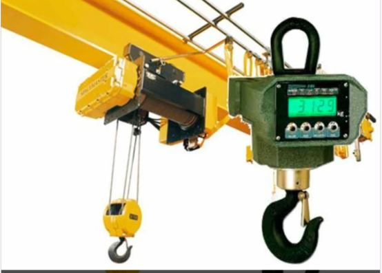 | Crane Load Indicators ₹87000 Price: ₹87,000/Piece The 50 Ton Crane Load Indicator from SmartITA Pvt. Ltd. View product → |
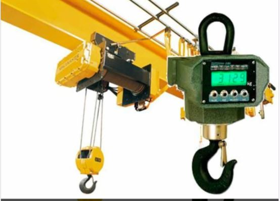 | Crane Load Indicators ₹35000 Price: ₹35,000/Piece The 5 Ton Crane Load Indicator from SmartITA Pvt. Ltd. View product → |
Frequently asked questions
How does a crane load indicator become an automation signal?
A load pin or rope-tension sensor measures force, and the indicator converts it into a load value for display, alarms, relays or plant-control communication.
Should you choose a load indicator, SLI or LMI?
Choose a load indicator for load measurement, an SLI for safe-load monitoring, and an LMI when the system must account for load moment, radius and operating configuration.
How do you choose between a 5-ton and 50-ton crane load indicator in Pune?
Select the system from the crane’s rated capacity and actual load path, then verify sensor range, overload margin, accuracy, hook-block weight and lifting attachments.
What should you specify before integrating a crane indicator with plant automation?
Specify the alarm setpoints, relay outputs, analog or digital signals, communication protocol, power supply, enclosure requirements and fail-safe behaviour.
What must commissioning cover after installation?
Commission the complete installed system by checking sensor mounting, calibration, displays, alarm setpoints, outputs and automation responses under controlled test loads.
Related products
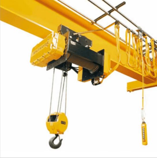 | Crane Load Indicators ₹48000 Price: ₹48,000/Piece The 10 Ton Crane Load Indicator from SmartITA Pvt. Ltd. View product → |
 | Crane Load Indicators ₹62000 Price: ₹62,000/Piece The 20 Ton Crane Load Indicator from SmartITA Pvt. Ltd. View product → |
 | Safe Load Indicators for Cranes Safe Load Indicators for Cranes SmartITA Pvt. Ltd. designs and manufactures advanced Safe Load Indicators (SLI) for Cranes to improve operational safety and prevent crane... View product → |
 | Crane Safe Load Indicator ₹25000 Price: ₹25,000/Piece The Crane Safe Load Indicator (SLI) from SmartITA Pvt. Ltd. View product → |